Description
|
Lamborghini
part number
|
OEM manufacture
part number
|
notes
|
|
|
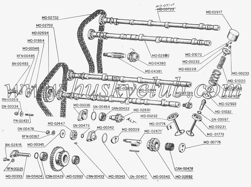
chain, cam - 2ea
|
MD-02702
|
Regina
ASA 35, made in Italy, double strand, rivited construction,
3/8
pitch, 3/16 roller width, .200" roller dia, |
93 links + master. |
|
|
Cup, cam - 24ea
|
MD-02917
|
|
|
Countach, Jarama, Espada, Miura, Alfa
|
|
shim, valve adjust
|
MD-01072
|
8mm x 1.5 thru 3.5mm fits Lambo 1964-1989 v12
Alfa shims, valve lash caps 8mm
|
|
Alfa 1.5-2.5
Alfa 2.525-3.0
|
|
keepers, valve - 48ea
|
MD-00233
|
|
|
|
|
keeper, valve - 24ea
|
MD-00228
|
|
|
|
|
spring, inner valve
|
MD-01020
|
46.5mm long, 22mmID, 3.425mm wire, 6.33coils
|
|
|
|
spring, outer valve
|
MD-02033
|
46.5 long, 32 ID, 3.93 wire, 5.5 coils
|
|
|
|
washer, valve spring shim
|
MD-02903
|
|
|
|
|
guide, valve
|
MD-01032
|
|
|
|
|
seal - oring?
|
GN-03097
|
not used
|
|
|
|
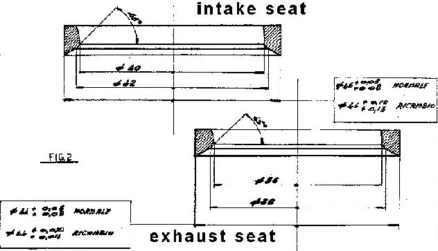
seat, intake
|
MD-00231
|
OEM berylium?
|
|
http://www.babcox.com/editorial/ar/eb40332.htm
|
|
seat, exhaust
|
MD-0232
|
OEM berylium?
|
|
http://www.babcox.com/editorial/ar/eb40332.htm
|
|
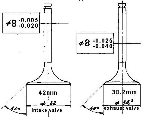
valve, intake
|
MD-01773
|
LIVIA 01773, 42mm, 8mm, 96.5mm
|
|
|
|
valve, exhaust
|
MD01774
|
LIVIA 01774, 38mm, 8mm, 95.6mm
|
|
|
|
o-ring,
|
GN-00464
|
|
|
|
|
o-ring,
|
GN-00473
|
|
|
|
|
o-ring,
|
GN-00407
|
|
|
|
|
o-ring
|
GN-00424
|
|
|
|
|
bearing, idler - 2ea
|
CRN-00433
|
K RIV -01A=6203 Car 053 ITALY 3 |
17 x 40 x 12 |
|
|
bearing, idler - 2ea
|
CAN-00478
|
double row needle
|
30 x 35 x 25.6
|
|
|
bearing, idler MD06291/MD04381 - 4ea
2 piece roller brg, outer race/inner caged rollers and race
|
GRN00433
|
outer - L RIV 1DAG/22 ITALY 2
inner - L RIV 1DA/V22 ITALY 2
|
50 x 14
22 x 14
|
|
|
bearing, idler - 2ea
|
CSN-00429
|
K RIV -01A=6203 Car 053 ITALY 3
|
17 x 40 x 12
|
|
|
need info to complete table information
http://www.sivalves.com
http://www.raceenginedevelopment.com/pages/694927/index.htm
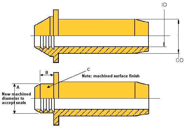
Fitting Valve guide seals to early V12 Lamborghini engines - October 2007 - in progress, need input
1) using stock valve guides, modify the stock , installed guide to accept valve seals.
-heads off engine, valves out.
-8mm ID valve guide is used to pilot the cutter head arbor.
-cutter head trims off the upper exposed OD of the valve guide to create a surface for a valve seal.
|
|
2) using new design replacement valve guides with seals fitted
-heads off engine , valves out
- remove old guides per factory proceedure.
- install new guides
|
|
possible helpful links for seals and tools
|
http://www.qualcast.net/pdf/vssprog.pdf
|
valve seals
I recommend using stem
seals. If you plan to do a rebuild on the V12, you will be replacing
the valve seats, valve guides, and probably, the valves themselves. So
it is no big thing to have the valves made with a circular slot to
accomodate the seals. There are many out there that will work fine. My
own engine (400 GT) has seals that were originally made for a BMW. With
our engines, there are several quarts of oil in the cam chambers at any
given time when the engine is running. The seals don't eliminate oil in
the guides, but they do reduce it and likewise, they reduce the amount
of oil that ends up in the combustion chamber, and therefore the oil
consumption. Just my humble opinion, as they say. Other opinions
welcome! Jack
Good comment but not enough detail to let others follow
Yes I have used Valve Stem Seals that
I had purchased from GTCP that are for a Ferrari, Had to disassemble
the heads completely and set them up in my Mill and I purchased a
cutter for the 8mm valve stem guides and cut the guides for the
positive type seals. Sure eliminates the puffs of smoke on restarts. I
would highly recommend doing them even if you have to seek out a
reputable machine shop. B/R Dave
Good comment but not enough detail to let others follow
Valve Job
If the valves are the same
as a 400s countach, S I Industries has swirl polished performance
valves that will work with minor machining needed. They are a
Nissan/Datsun L-series valve 38mm head 8mm stem (exhaust), and 42mm
head 8mm stem (intake).The part #'s are 8002SG exhaust, and 8101E
intake. The stems needs to be shortened, and the intake head on the SI
valve is a 43mm, your machinist will know what to do. I paid less than
$10 a valve including 2nd day shipping. S I's # (805) 582-0085 - Greg
Excellent follow up from Greg 10/05
Craig, The valves needed to be cut to length and a
retaining groove made, the price for the machine work came to 300,
$12.50 per valve. Eastco( the machine shop) had me purchase 1 new
intake, and 1 new exhaust valve(original) to take measurements from. I
still have these valves if you are interested. The guides were a VW
Gulf or Rabbit bronze with seal provision, better than the
original guide that with its angular top strips the oil from the valve
stem, the original type of guides wear out quickly. 24 guides $300,
rubber seals $54, replace guides $100, and the valve grind ran $400.The
original seats were used. Hope this helps. I purchased valve shims from
GT Carparts. BTW all my valve springs tested out in good cond. I now
have about 2,000 miles on the engine rebuild, NO problems, and I'm very
happy with the machine work, and the parts used, not to mention the
savings from using quality parts that don't carry the expensive
Lamborghini name. Let me know if I can help in any other way. Good
luck, Greg
Re: valve guide removal
First
mike up all your valve stems to see how true they are. If the valve
stems are worn, replace the valves. Check the valve stem to guide
clearance with a dial bore gauge. Most engines need .0015" to .002"
stem to guide on the intake valves and .002" to .0025" on the exhausts.
Any tighter and the valves are likely to sieze in the guides. Much
looser and the valve job will be short lived. You might be able to get away with knurling and reaming the old guides.
I don't like doing this because it is a short term fix. Better off
doing it right the first time. If you do however want to go this route,
K-Line tools has the tooling - knurling tool and reamers. I think
Goodson sells their stuff. If you replace the seats, make certain you use seats compatable with
unleaded gas. Same for the valves. The valves can be custom made by
Ferrea, Rev, Manley, etc. No need to pay Ferrari prices. I believe Nick
has another source he uses if you want to give him a call. Steve
Excellent follow up from Steve
The method you descibed to remove the valve guides (predrilling to relieve and then use an internal drift) is correct. Drilling
the guide ID will relieve the press fit enough to drive it out with a
punch or air hammer without scoring the guide hole in the head. What you need is a core drill. The drilling is best done on a cylinder
head guide and seat machine but if you are careful, it can be done by
hand.
Sunnen part # VGS156A
.312" pilot, .490" core drill diameter
1-800-772-2878
Goodson part # CCD-468A
.312" pilot .468" core drill diameter
1-800-533-8010
Do not heat the head to 300 degrees! You can warm the head a bit but
the guides will come out at room temp once relieved. You should
get guides .001" to .002" larger in diameter to replace the
guides you remove. You need no less than .002" press fit to keep the
new guides in place. Steve
Head work
Hello tech help, We heat aluminum heads in a turbo oven that evenly
raises the
temperature of the head to 400 degrees and knock the guides out with a
stepped punch on an air hamer. The guides come out with very little
effort and virtually no damage to the heads. Valve seat removal
depends on the situation but on a 308, for example,
we just mill two apposing notches in each seat so that the thin wall in
the notched area collapses and the seats come right out with no head
damage. We always install over-size seats for which the seat pockets
have to be remachined so even if there was minor damage to the metal it
would not matter. Same for new guides which we have custom made for us.
Secure Installation of guides and seats depends on heating the heads
and pre-chilling the inserted seats and guides but most important is
extremely accurate machining, particularly of valve seat pockets, to
ensure an interferance fit you can rely on. Robust and accurate tooling
for driving in the chilled components is also critical. The head has to
be re-heated frequently and properly supported. The inserted part
should be kept in a freezer untill just before use and hosed down with
Minnesota Fast Freeze, or a similar product, after mounting it on the
driving tool ready to install and then get it in there FAST before it
heats up. After everything has cooled, the guides have to be reamed to
fit the
valves and the seats have to be machined to line up with the guides so
that the valves will seat correctly. properly done head work is
not cheap for a reason - a lot of
pains-taking work and expensive, specialized tools, equipment and
parts. And you can't be annal enough if you want the job to last. Wil
guide removal
JBill Badurski- FCA Technical
Chairman, New member, Username: Badurski, Post Number: 2, Registered:
06-2003RV, I've got to replace the valve guides on a pair of Daytona
heads. Any tips or suggestions other than local heat and driving them
out? JRV New member
Username: Jrv Post Number: 186 Registered: 05-2003
Posted on Saturday, July 26, 2003 - 08:09 am: Hi Bill, I was taught to
drill the guide itself with a step drill 75% of the lenght of the guide
(basically 90% boss depth) first leaving only about .20 -.30 thousanths
wall thickness left. Then heat, and press or drive out with a drift.
The drift sits on the internal ledge left by the under drilling. By
drilling all the center material out of the guides it releases the
compression fit and prevents the guide from expanding the boss on it's
way out. It is important to drill striaght to prevent going
into the boss material. The best type drill bits for this
operation have a stepped tip to aid in alignment and to keep things
centered to avoid going thru the guide wall as the cut coes deeper.
It's nice to start on the seat side so the guide is removed out the way
they go in. But sometimes on well worn guides the drill bit won't
center well enogh for the long cut. If you need a better
explanation of the procedure we can talk on the phone. Regards, JRV
Valve Seat Installation Procedures
by Larry Carley, Technical Editor
lcarley@babcox.com
Valve seats are an extremely important
part of a cylinder head because the seats cool and seal the valves.
They also support the valve when it closes, which affects both
valvetrain geometry and valve lash. If a seat is damaged, cracked,
loose, receded or too badly worn to be recut or reground, it can cause
a variety of problems: loss of compression, valve burning, valve
failure, valvetrain wear and breakage, even head and valve damage if
the seat comes loose.
For that reason, replacing valve seats
is often necessary when reconditioning aluminum or cast iron cylinder
heads. Another reason to replace a seat is if a valve has broken
because the seat is not concentric with the guide. Misalignment between
the seat and guide causes the valve stem to flex every time the valve
closes. Eventually, this flexing leads to metal fatigue and valve
failure. When this happens, the counterbore must be remachined (if the
head is salvageable) to realign the seat with the guide.
New seats may also be required if a
cylinder head has been straightened or welded, if there’s any evidence
of corrosion around the outside diameter of a valve seat, or if the
engine is being converted to run on a dry fuel such as propane (LPG) or
natural gas.
Integral seats in cast iron heads are no
less important even though the seats are part of the head itself. An
integral seat may have to be cut out and replaced with a new insert if
the seat has receded, is badly worn or damaged.
How Often?
Some experts say when late model aluminum heads are reconditioned
the valve seats should always be replaced to maintain correct
valvetrain geometry. This applies to overhead cam engines as well as
pushrod engines. It’s expensive but is usually necessary to restore
proper installed valve height and valvetrain geometry.
Rick Emert, product and technical
services manager for SB International, says most valve seat failures
(more than 50 percent) are due to one of two things: misapplication
(wrong valve and seat combination) or valvetrain "mismotion" (incorrect
valvetrain geometry or lack of seat/guide concentricity). He also
explains that preignition causes a lot of seat failures, too.
"When seats get too hot, microwelding
occurs between the valves and seats. The valves are harder than the
seats so microscopic particles of metal from the seats stick to the
valves," says Emert. "When the engine cools, these particles are then
washed into the exhaust. This causes rapid recession of the seats and
is most common in dry fuel (LPG or natural gas) engines."
Emert said another reason for replacing
seats in some late model heads is because the OEM powder metal seats
become too hard to machine. Many late model gasoline engines with
aluminum heads from Ford, GM, Chrysler and many imports are
factory-equipped with sintered powder metal seats. Powder metal seats
are used because they are harder and more durable.
Powder metal seats combine various
materials to achieve special properties. Many powder metal formulas
work-harden as the engine runs. A new powder metal seat that has a
hardness of RC 25 when it is first installed will develop a hardness of
RC 40 to 50 after several thousand miles. Seats that hard are difficult
to refinish by cutting, so one alternative to grinding is replacing the
old seats with new powder metal or alloy seats.
Emert says his company recommends alloy
seats for most applications because they are easier to machine. "We
have eight different alloys in our product line, and each one is
engineered for a specific type of application." His company’s two most
popular alloys are "Cast XB" (an iron-based alloy), and "N-Series" (a
nickel-based alloy). SB International also has powder metal seats for
those who want to install the same kind of seats as original equipment,
Emert says.
"But we don’t recommend installing
powder metal seats in diesel engines because powder metal seats can’t
take the heat and compression in this kind of application. They may
shatter," says Emert.
Other valve seat manufacturers offer a
variety of different alloys for valve seat inserts, as well, including
various powder metal formulas. But powder metal has been slow to catch
on in the aftermarket. Although engine rebuilders are seeing more late
model heads, many still prefer to use alloy inserts.
However, Bill Dolak of Dura-Bond says
traditional cast iron seats won’t hold up well in late model engines.
He recommends one of two different alloy seats depending on the
application, either the "30000 Gold Series" valve seat inserts made of
finely dispersed tungsten carbide in a matrix of tempered tool steel
and alloy iron particles, or his company’s "70000 Diamond Series"
inserts which use a higher temperature mix of tool steel and tungsten
carbide. He says the 30000 Gold Series seats are easily machined and
offer good wear and heat resistance for naturally aspirated and
turbocharged engines. For high performance, heavy-duty and dry fuel
applications he recommends the higher temperature 70000 Diamond Series
inserts.
Dale McKitterick of Precision Engine
Parts clarifies what alloys are appropriate for which applications. His
company offers high chrome alloy seats (which are good for unleaded
gasoline engines in most passenger car and light truck applications),
nickel alloy seats and M2 tool steel alloy seats (for severe duty, high
temperature applications), ductile iron seats (popular with many race
engine builders) and beryllium/copper seats (used mostly in megabuck
high end racing engines). McKitterick says he also has powder metal
seats, but only a few customers have asked for them.
Qualcast, Tucker Valve Seats, Martin
Wells and others all offer a variety of different alloy seats for
various types of engine applications. The important point here is to
choose a replacement seat that is right for the application. Higher
load, higher temperature applications require harder seats. Follow the
recommendations of the valve seat insert suppliers because they know
what works best in each type of application.
Cast iron inserts are still used for
light duty intake valve applications but should never be used on the
exhaust side. The metal is just too soft to withstand the operating
temperatures. For exhaust valves, a hard insert made of high chrome
stainless steel, high nickel alloy or a heat resistant alloy must be
used. Stellite inserts, which are made of a nonmagnetic cobalt alloy
and are the hardest inserts available, are recommended for the exhaust
valves in heavy-duty, high temperature engines and those that burn dry
fuels such as propane or natural gas.

Tom Tucker of Tucker Valve Seat,
says 440 stainless steel seats or Silicone XB (an iron seat with 18
percent chrome) are the most popular aftermarket seat materials today.
But he also stressed the importance of choosing a seat that’s designed
for a specific application.
"We have a tool steel tungsten carbide
material for natural gas applications that holds up especially well. We
also have an ‘E’ series material that provides superior hot hardness
but is not as hard or abrasive as #3 Stellite."
Roger Klump of Martin Wells says his
company has been selling its Well-Tite alloy for more than 30 years and
he’s never seen a failure with the product. "It has the same wear
characteristics as a 52 RC Stellite-type of product but with a hardness
of only RC 35 to 37," explains Klump. "The Well-Tite alloy contains 42
percent nickel, which provides good heat transfer and valve cooling. It
also contains 10 to 12 percent chrome for oxidation resistance, and 7
percent moly for toughness."
Preliminary Steps
Seats should not be replaced until the head has been thoroughly
cleaned and inspected. This includes checking for cracks (especially
around and near the valve seats) and checking the deck surface and cam
bore for straightness. Any welding and/or straightening that may be
needed must be done before remachining the valve seats or installing
new inserts.
Also, the valve guides should be
replaced or reconditioned before the seats are machined. Concentricity
between the seat and guide is absolutely essential for a proper
alignment, good compression and long term valve durability.
The cylinder head must be dimensionally
and geometrically within specifications before seat counterbores are
machined. That includes cylinder head thickness, valve guide
clearances, concentricity and perpendicularity. There should be no
warping, twisting or any type of misalignment anywhere in the head.
Seat Removal
The first step in seat replacement is removing the old seats. A
variety of methods can be used to remove valve seat inserts from
aluminum heads. Putting the head in a cleaning oven is sometimes used
to loosen the seats enough to where they may fall out. Knowing the
secret password necessary to keep good seats in place while allowing
the damaged heads to release is critical (of course, there is no
password). Using an oven in this way is a lengthy process that offers
no real "predictability" regarding seat loosening.
Another method that does not involve
heat is to use a cutter slightly smaller than the outside diameter of
the existing valve seat insert to cut away most of the old insert (this
works on softer alloy seats but not very well on powder metal seats).
Stop cutting when the old seat begins to rotate in the head. What
remains of the old seat can now be easily removed.
Another method of cutting out a seat is
to use a die grinder to slit and weaken the seat. Just be careful not
to cut all the way through the seat and into the counterbore.
Prying out valve seats also works if
there is enough of a lip under the inside edge of the seat, but this
technique also risks damaging the counterbore if not done carefully.
To remove hard seats, arc weld a bead
all the way around on the seat. As the bead cools, it will shrink and
loosen the seat. For more information on this procedure, see the March
issue of Engine Builder, page 28, "The Whys and Hows of Welding
Aluminum."
Another trick is to place a valve that’s
somewhat smaller than the seat in the head and weld the valve to the
seat. The valve stem can then be used like a driver to push out the
seat.
Once the inserts are out, check for
cracks or erosion damage under the seats in the counterbores – a common
problem on many aluminum heads. If cracked or eroded, the metal can be
rebuilt by TIG (tungsten inert gas) welding, and remachining the head
to a new seat.
Cutting Counterbores
Many experts recommend recutting the counterbores to accept new
oversized seats. Some engine builders will install new standard-sized
inserts in the existing counterbores. It works on some large cast iron
cylinder heads with thick walls, but it’s risky on most automotive
applications. The recommended approach is to remachine the counterbores
to accept oversized inserts. This allows you to control the
interference fit between the seat and head so the seats don’t come
loose.
Recutting the counterbore also allows
you to control runout in the counterbore and concentricity with the
valve guide. The counterbores must be smooth, round, have flat bottoms
and be centered to their valve guides for proper alignment
and good heat transfer between the seat and head. The final dimensions
of the counterbores must be within .0005˝ for the proper fit.

If a counterbore is too rough,
distorted or out of round, it won’t make good metal-to-metal contact
with the seat. It can also distort the seat. This will reduce heat flow
from the seat to the head and make the valve run hot. That you don’t
want because it leads to valve burning and warranty problems down the
road.
If you’re replacing an integral seat in a cast iron head (and the cylinder
head has enough thickness to accept a new seat), the counterbore should
be cut to a diameter approximately .100˝ larger than the valve head
diameter. The inside diameter of the replacement seat will typically be
about .100˝ smaller than the valve head diameter and require a depth of about .188˝ to .250˝ depending on the application.
Accurate
cuts also require proper fixturing. Keep your tooling setup as "short
and tight" as possible to assure maximum rigidity. The less deflection
in the tooling, the more accurate the dimensions of the cut and the
greater the concentricity of the counterbore.
Be careful not to distort or put a twist into the head when clamping it to a fixed rail holding fixture.
You’ll get the most accurate cut with
correct size pilots (which must be straight), and using the correct
spindle speeds and feeds. Machining recommendations vary depending on
the type of equipment and tooling used, but Dura-Bond recommends using
cutting oil and a spindle speed of 400 to 600 rpm when cutting valve
seat counterbores in aluminum heads. When cutting cast iron heads,
Dura-Bond recommends using no lubrication and a slower cutting speed of
100 to 250 rpm.
Something else to keep in mind when
cutting counterbores is that the seats for many late model heads don’t
go by fractional sizes anymore. Seat sizes can vary considerably so
using a fixed size cutter is not the best choice. An adjustable cutter
will provide the flexibility you need to properly size the counterbores.
Interference?
The recommended amount of interference between the valve seat
insert and head may vary depending on the size of the insert, the type
of insert (alloy or powder metal) and type of head (cast iron or
aluminum). The best advice is to use the amount of interference
recommended by the OEM engine manufacturer.

Too much interference runs the
risk of cracking the head while too little interference increases the
risk of the seat coming loose or falling out. One of the leading causes
of seats coming loose, however, is not the amount of interference
between the seat and head but elevated operating temperatures. Anything
that causes the exhaust valve to run hot may also cause the seat to
loosen.
Philip Carrasco at Tucker says seats may
require anywhere from .002˝ to .010˝ of interference depending on the
application and the roughness of the surface in the counterbore. For
aluminum heads, an interference fit of .005˝ to .007 ˝ is commonly
used. For cast iron heads, .003˝ to .005˝ is about right.
Martin Wells’ Roger Klump says he recommends an interference fit of .005˝ to .006˝ for everything, aluminum and cast iron.
Rick
Emert of SB International says he tells his customers to use .005˝
press fit when installing seats in cast iron heads, and .007˝ minimum
in aluminum heads regardless of what type
of valve seat inserts they are installing. "We do not recommend using
any type of locking fluid, staking or peening when installing seats.
You should be able to put a concentric seat into a concentric hole with
the right amount of interference and have it stay there," says Emert.
Carrasco, on the other hand, says a lot
of engine builders have had success using a locking fluid. "They tell
me it helps fill any voids between the seat and head for improved heat
transfer and valve cooling. You don’t see many production engine
rebuilders doing this but you do see smaller shops doing it," said
Carrasco.
Seat Installation
Installing the new seats once the counterbores have been cut is a
fairly simple procedure. A piloted driver is used to push the seat into
position. Many aftermarket seats have a bevel or radius on the outside
lower edge to make installation easier. Make sure this side faces down
when installing the seat.
Some engine builders preheat the head or
chill the inserts in a freezer or with nitrogen prior to installing
them to make the job easier. Others say this should not be necessary if
you use the normal amount of interference fit. Even so, it’s another
trick that may come in handy on a problem head or application that
requires something out of the ordinary.
Seat Finishing
After the seats have been installed, they can be finished as
required. The guides must be reconditioned or replaced before doing
this, however, because all seat work is done by centering off the
guides.
Seats should be as concentric
as possible for a tight compression seal and proper valve cooling. The
rounder the seat, the better. Seat runout should not exceed .001˝ per
inch of seat diameter. Some shops aim for .0005˝ or less of runout.
The best way to check concentricity is with a runout gauge. Pulling
vacuum on the valve port with the valve in place is another method for
checking the mating of the seat and valve. But the ability to hold
vacuum is no guarantee of concentricity. Both methods should be used to
check the quality of your work.
Seat width is also important for good
heat transfer, proper sealing and long valve life. If the seat is too
narrow, wear resistance and heat transfer can suffer. And if the seat
is too wide, there may not be enough pressure to provide a tight seal.
A wide seat also tends to trap deposits that can hold the valve off its
seat. This too, can reduce heat transfer as well as compression. As a
rule of thumb, the ideal seat width for intake valves is usually around
1/16˝. For exhaust valves, it’s 3/32˝ – or whatever the manufacturer specifies.
The point at which the valve and seat
mate is also important. If the area of contact is too high on the valve
face (too close to the margin), the valve may be sunken into the head.
This increases installed height, upsets valvetrain geometry and
restricts free breathing. If the area of contact is too low on the face
(too far from the margin), the valve will ride too high on the seat. As
the engine warms up and the valve expands, the contact point moves down
the valve face away from the margin. The valve may lose partial contact
with the seat causing it to lose compression and run hot.
Ideally, the valve should contact the seat about one third of the way down the valve face (about 1/32˝ from the margin) so there is about 1/64˝ of overhang between the margin and top of the seat. EB
BACK TO BASICS – Valve Seats
The most critical sealing surface in
the valve train assembly is between the face of the valve and its seat
in the cylinder head when the valve is closed. Leakage between these
surfaces reduces the engine’s compression and power and can lead to
valve burning. To ensure proper seating of the valve, the valve seat
must be:
- Correct width
- Correct location on the valve face
- Concentric with the guide (less than .002˝ runout).
The
ideal seat width for automotive engines is 1/16˝ for intake valves and
3/32˝ for exhaust valves. Maintaining this width is important to ensure
proper sealing and heat transfer. However, when an existing seat is refinished to make it smooth and concentric, it also becomes wider. Wide seats cause the following problems:
- Seating pressure drops as seat width increases.
- Less force is available to crush carbon particles that stick to the seats.
- Valves run cooler, allowing deposits to build up on them.
The
seat should contact the valve face 1/32˝ from the margin of the valve.
When the engine reaches operating temperature, the valve expands
slightly more than the seat. This moves the contact area down the valve face. Seats that might contact the valve face too low might lose partial contact at normal operating temperatures.
Like valve guides, there are two types
of valve seats – integral and insert. Integral seats are part of the
casting. Insert seats are pressed into the head and are always used in
aluminum cylinder heads. Most pre-1978 integral seats are soft cast
iron. After 1978, most manufacturers began to produce cylinder heads
with induction hardened cast-iron seats able to withstand the higher
heat of exhaust applications. Insert seats are added to the cylinder
head after casting, or as replacements for worn integral seats.
from the book:
"Complete Automotive Engine Rebuilding and Parts Machining" |
Now for some added
confusion/clarification originating from Down-Under !!!! :-))From my
Italian Espada Manual, there is a section on valve springs, which I
have hopefully translated correctly.There are 2 part numbers given for
both inner and outer springs and 2 different sets of figures - it
appears that there are differing springs for older and later Espada
motors. On the parts listings I have, the 2 numbers appear on different drawings - the second number in each case seems to be from the later engines
Outer Valve Springs
Part Number 1202083
Uncompressed length - 49mm
Valve Closed length - 35mm at 20kg +/- 1kg
Valve Open length - 28mm at 28.6kg
Part Number 1213133
Uncompressed Length - 59mm +/- 1.2mm
Valve Closed Length - 36mm at 36.5kg +/- 1.5kg
Valve Open Length - 26.5mm at 51.6kg +/- 2kg
Inner Valve Springs
Part Number 1201020
Uncompressed length - 49.8mm
Valve Closed length - 37mm at 25kg +/- 1kg
Valve Open length - 26.5mm at 45.6kg
Part Number 1213132
Uncompressed Length - 48mm +/- 1mm
Valve Closed Length - 36mm at 26.2kg +/- 1kg
Valve Open Length - 26.5mm at 47kg +/- 1.8kg
These are direct copies of the values – why some have tolerance values,
and other don’t, I don’t know. Likewise some of the figures seem a bit
odd – lengths especially – they are copied accurately, again I don’t
know why….
There is a statement regarding the valve spring numbers which I can't
understand - can somebody else translate for me please. This concerns
the outer springs
rif.lamborghini 1202083 fino alla 1150a vettura, rif.lamborghini 1213133 dalla 1151a vettura
Likewise there is the same statement using the two part numbers for the inner springs
rif.lamborghini 1201020 fino alla 1150a vettura,rif.lamborghini 1213132 dalla 1151a vettura
Given that there are two different spring part numbers and
corresponding values for the Espada, I would tend to believe that there
would be other part numbers and values for the higher power engines,
especially the Miura, LP400 and LP400S. Likewise the older engines in
the GT350 and GT400 which have lower power engines may have other part
numbers and values. Knowing the variations that occur in the cars, I
can't believe that Lamborghini would have all the valve springs of a
standard size and value.
John - April 08,05
the following is an interesting Q&A at FerrariChat.com
valve guide removal and seats
Hello tech help,
i am in need of some exacting help on locating a a supplier of the
correct type drill bits for removing valve guides. My guides are 8mm
bore (but slightly worn), the OD of the guides are 13mm. Aluminum heads
of course with bronze style 60's era valve guides. I understand a
"pilot" drill bit with an 8mm guide is what i need to take out the bulk
of these guides prior to knocking them out. Maybe 12mm bit. 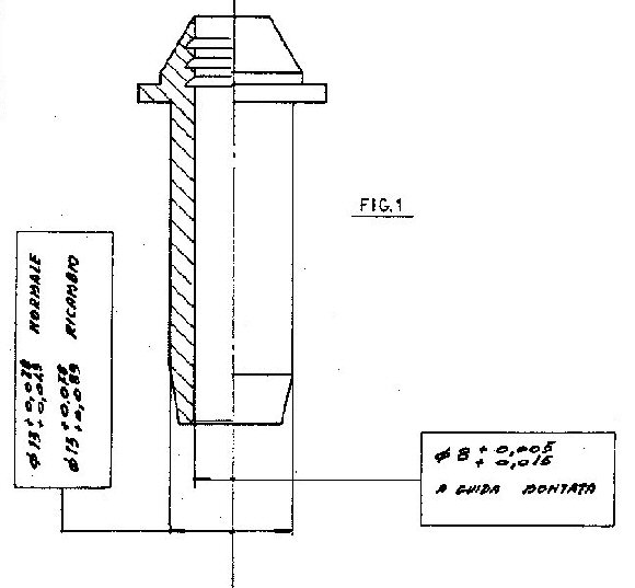
I have been told the technique is to drill away 80% of the internal
bronze material, then using a custom punch to fit this new internal
"step", heat the head to say 275F and punch them out.
Who would supply a piloted drill bit? any help would be wonderful. thanks
Craig
fatbillybob says - NO
NO NO you are getting the bum steer! DIY'ER at home you heat in pizza
oven to 300 degrees F. and drive out with an air hammer made on a lathe
to the exact size of the valve guide. There is no drilling needed. If
you are just our of spec sometimes you can leave the guide and knurl
them at a machine shop and that is just enough to prevent oil passage.
Often all you really need the 1st time is new oil seals. Ferraris like
355's and 308's have been known to eat these seals but yet have valves
and guides in spec.. You will need a machine shop to replace the
guides, square them to the head, measure run out to the valve seat,
angkle the seats, cc the head mill the deck. Therefore why not let them
remove the guides too if you don't have the right tools? It is very
important to do these little details properly. Forecxample if you deck
the head too much to increase the CR you have to shim the cams to
maintain the timing relation. Are you ready for these kinds of things?
Fred2 says -
The instructions that you are talking about are the same that I was
given for removing the guides from an aluminum alfa head. The reason
for drilling the guides, was that the punch would act on the far side
of the guide, and "Pull" it out. If you hammer on the side in the port,
you may mushroom the guide, and
wear the cylinder head. This would result in a sloppy fit for the new
guide. If you decide to drill the guide, the hole that is in there will
act as your pilot. You would have to work real hard to NOT drill the
hole concentric. If you split the difference between the OD and the ID,
you should be OK
on Drill diameter. Plan ahead, and first find a drift with the diameter
to match the drill you will be using.
P400 says -thanks
fatbillybob and fred2, i understand that this work is fairly simple for
a DIY project. i am told that Neway tools may have all the step drills,
step drifts, valve seat cutter tooling, etc. Are you aware of any other
tool suppliers?
Is there any experience to guide me in purchasing guides, seats and
valves from a high quality supplier......maybe SI Valve? or Manley
Valve? or ? you folks are just great for help on this thank you Craig
MattMorgan"Kermit" says - Or
if you want to try a diffferent way yet, Use a 3/8" nc "gun tap" (they
push the chips out ahead of the tap,with an extension long enought to
reach most of he guide, the STD 2 valve bore is close to the drill size
for the tap as is.A variable speed drill is good here Tap the guide
3/4th of the way down from the top (let the tap follow the hole, and it
will center every time). out a threaded rod into the guide, add a short
block that has a center hole at the base long enough,. and wide enough
for the guide,. put a nut and washer on top, and either crank it with a
ratchet, or better yet, an air ratchet, and it pulls them easily. The
tapping removes enough to release, and the threads pull fro the inside,
a better way that hammering them, as they cannot mushroom.
HTH. Kermit
With an air ratchet, I have done both heads in under a half hour with no galling, etc
Fatbillybob says -
IMO you guys are doing way too much work. The guides are press fit with
heat expasion. When you heat the head those soft silicon bronze guides
drift right out with a simple drift and hammer. They never mushroom and
you never gall the head unless you are doing this cold. Some mechanics
do this cold and have no problem. Even heat is the preferred method. I
have done this cold and with a torch when oven was not available. The
right tool is what you need. Drilling just weakens the guide but does
not change its dimension or press fit. If you drill it enough to
severely weaken it you can 1) hit the casting if you do not stay
perfectly concentric 2) now have such a thin guide that it is difficult
to drift out. That is why the tool to do this job is called a drift
punch and is matched to the land and inner diameter of the valve guide.
90% of car makers have a special tool just for their application. Some
stuff can be done crudely in your garage but you need precise tools to
make sure the guide is in perfectly square and with proepr runout with
the valve on the seat etc.. This is much more precision oriented than
say ridge reaming a cylinder in the garage. But you can get 90% of the
way there by just slapping the parts in and hoping that manufactuer
tolerances are close enough for a decent fit and therfore decent
function. So yeah you could do it with Neway tools and a clean garage.
tomoshea says - I
have spoken to many specialist Ferrari engine rebuilders as I have just
completed a total top and bottom end rebuild on a 308 engine.
Interesting facts.
1) The amount of metal surrounding the inlet and exhaust valve guides
is not the same on the 308 this casues alignment problems when you
replace the guides!!!!, they "kink" when the heads cool down.
2) Ferrari had problems using already drilled guides in the factory and
getting the valves to line up with the centre of the the hole for the
seats.
3) To sort this out Ferrari fit solid guides in the 308 engine then
bored out the core so they could ensure alignment with the valve seat.
Now if you air jack or push out the guides that are in place (even with
the heads heated up) you will strip small amounts of aluminium off the
head and I can guarantee you from personal experience that you will
have problems aligning the the new guides/ valaves an seats.
All the guys that do this for a living have told me that you need to
drill out the guides in place to almost the full diameter and then use
a drift to "push" out what ever thin amount of metal is left (this
should be done with the head hot)
This makes rebuild considerably easier and will save you time in the long run.
However if you were going to replace the seats ignore all of the above.
Regardless always heat the heads and then air cool the guides before you try to remove them.
Don't do it cold one professional told me of a very nasty expensive experience he had when he did this!
fatbillybob says of tomoshea above - Urban legend to justify those high Ferrari engine rebuild prices. I
have never seen this and rebuilt perhaps 4 Ferrari engines in my time,
myself, with proepr tools , line bored cam journals the whole bit.
Actually, these casting are surprisingly good adn you could do this in
your garage with very few tools and get 90% close for a decent running
car.
dbcooper says -We've
done many,many heads where we air hammered the guides out cold and have
had 0 problems/mistakes. whether this method is correct or not is
reflected in the numbers if ya ask me.
fatbillybob says of dbcooper above - O.K. listen up folks here is a guy who speaks the same truth I speak.
I've done 4 engines myself from cradle to grave and many more indivdual
heads. This echos my experience too but I have a mixture of doing this
job with all the best tools and with no tools.
You must be lucky! I have rebuilt one top end and had up to 5 tho out on some of the new
guides (not a major issue but did require cutting the seats).
Superformance, QV, Nick Cartwright and others in the UK, who by the way
was never going to benefit from the advice they gave me, as I was doing
the work myself with a local machine shop in Ireland advised me that
based on all there years of experience they always drill out and then
punch, for the reason quoted above.
Horses for courses!, you might have touch that others don't have when it comes to getting stuborn guides out of Ferrari heads.
By the way my engine was a 79 Ferrari and the castings were not the best finished heads I had ever seen (understatement).
Artvonne says - Interesting
subject, as I need to contemplate my direction on this as well. What
are others thoughts on some of the old industry fixes, such as:
Knurling the guide, Sleeving the guide
I have always been of the opinion that if the guide was worn it
should realistically be replaced, that those two "options" were
considered bandaids. However, I also seem to recall that many
performance shops would sleeve the guides with a better bushing
material that allowed the valve to keep sliding and stay lubricated at
high speed and temperature. Also that with real tight guides, some
would not run a seal, but allow the oil to go were it wanted, with only
the clearance to hold it back, and thus the name "Valvoline" was born.
The proverbial smoking Italian car that always needed that special
tuneup to clear itself after long periods of slow running.
P400 says -Thanks for the help,
i went to Neway tool site -
http://www.newaymfg.com/frame.htm
they show the valve seat cutting tools and the valve refacer tools, but not showing guide step drills or drifts.
my question for the folks predrilling guides -
what company or resource do you use for drills and drifts?
i would see the drill having a 8mm guide to follow the existing hole and then step up to 11.5 or 12mm.
who provides these?
any help on this is great. the existing guide material is bronze.
Craig
fatbillybob says of tool search above - I f you can't find it make it. You can take an existing air hammer tool
and chuck it in a lathe and spin it down. If you don't have a lathe you
can find a tool that is less than the overall diameter and has the
pointed tapered end. Those air hammer bits are very standard. Then you
break out your file and file a land in the tapered point to match the
land of the guide 11mm? and around you file until about 8mm diameter,
you do not need to be precise here, and there you go. Then you heat the
tool red hot with a torch and quench it in oil..voila!
Artvonne says - Well,
there must be some reason all the aircraft mechanics heat all the jugs
up with a rosebud torch before removing or installing guides. And it
matters not who made the engine, what model it is, or year, or size. I
am able to recognise that maybe its done that way simply because thats
the way its always been done, and there may not be a valid reason, but
then again.....
Its funny, but not real funny, that most cars for example can last
for years and run well past 100K miles in original condition, and then
it gets cylinder head work, and some new valve seats. Next thing you
know, you see this engine that dropped a seat, and the damage can be
absolutley amazing. I guess the thing to keep in mind, is that a guy
dont have to work on Ferrari's to know mechanics, and that just because
someone calls themselves a mechanic, doesnt mean you want thier help
fixing your John Deere. Its almost like for every good mechanic there
are about 10 others who can screw up things so awful you were probably
better off if they never touched it. I honestly cannot count the times
I've taken parts to an aircraft mechainc, simply because I couldnt find
anyone else qualified.
I would also agree here, that at least with this 308 motor, I can
see nothing so exotic that a good general mechanic shouldnt be able to
work on it. And simply looking at the V-12's and at parts books they
seem equally the same. But you say that F word and either everyone runs
for cover, or they smile nice and ask for vast volumes of your money.
To wit, I was quoted over $2K per head for a standard valve job by a
shop in the twin cities. They had done some work on a 355 and now
thought thier crap didnt stink.
Mark says -
My previous occupation was a tool and die maker, I have a lot of
experience driving punches and bushings in and out and counterboring
holes. I agree that "drilling-out" the guide would relieve a lot of
pressure from the interference fit. If I were going to drill the
guides-out I would probably use a counterbore and a regular hand drill.
Keep in mind, brass and bronze have some bad machining characteristics
for drilling in that a sharp cutter can catch and act like a tap and
the cutter will rapidly and uncontrollably be pulled right thru the
material. With a hand drill it should be easy to control, but in a
milling machine with a high chip load it can pull the part out of a
vise and cause a lot of damage. In most cases when drilling bronze,
people take a stone and lightly dull the edge of the cutter.
As for heating the head, I'm not sure I would recommend doing this
unless the guide was going to be cooled just prior to removal. The best
way may be to heat the assembly and then "squirt" liquid nitrogen into
the guide (to shrink it) and use a drift to knock it out. The reason
that I would probably not heat the head and drive the guide out is
because I think bronze has either a similar or higher coefficient of
expansion then aluminum; therefore heating would likely increase the
interference, not improve it. However, if the assembly was heated and
then the guide was cooled it would come out most easily. Even cold
water squirted thru the guide in a heated head would help.
On motorcycles, I have sqirted them with penetrating oil then knocked
them out cold. For installation, I would reccomend freezing the new
guides and install into an oven heated heated head--they slip right-in.
Prior to putting the guides back in it is important to clean and hone
the hole out. They have some of those hones with the balls of stones on
--these would work great. You will not remove hardly any material -- it
would take some serious effort to remove even .0002”. A couple of light
passes with a hone will refinish the hole and will work wonders to
really facilitate installation.
As far as locating counterbores, a machine shop supply firm would have them. Do a search here for counterbore or spotface http://www.mcmaster.com/
check pages 2319 and 2320. There is a place in Paramount, Ca, (Cal
Aero) that randomly sells these interchangeable cutters used by the
pound. I have a few, in fact I have one that looks like 3015a22, but
has about a 1/16 radii in the corners. Send me an email and I’ll send
it to you, you can try it/use it for free. I only have a ¼ inch pilot,
but this could be “shimmed-up” to .3125” with a piece of brass tube
from a hobby store.
Keep us posted on your progress. Mark
P400 says -thanks for all the input!
i have found a valuable pdf catalog of possible interest to all in this valve work mode.
http://www.pirate4x4.com/tech/billav...ne%20tools.pdf
quite a few tools for all types of work are available
core drills, knurling or spiraling, all types of valve seat equipment, etc
i will need time to digest this catalog.
my OEM stems look within tolerance.
this is a vintage car for me to zoom around in, but i am not racing for championship points. nor is this a commuter car.
I am considering -
knurling guides
having valves professionally refaced
having seats professionally refreshed
reassemble
this may fit my 200 miles a year plan for this V12 car.
however i am not sure it would not be best to renew all, replace seats and valves with modern gasoline compatible materials.
If any of you wonderful folks have purchased seats, valves and guides recently, what vendors and materials did you use?
Manley? Ferrea? SI? Rev? or others?
any help would be fantastic and probably help all involved
Craig
Atrvonne says - Well,
we got the guides covered, now what about this guys other questions,
like were has anyone gotten thier parts from, and how do you guys
remove and install seats? None of us, especially me, want any seats
falling out.
dbcooper says - out cold. in hot - we
pounded them out cold and heated the heads with a propane coleman stove
to heat heads before guide install.sorry for not pointing this out
before.out cold no problem with air hammer.We also just bought storage
jug/thermos to super cool with liquid nitrogen for liners and guess
will use for guides too?
wildegroot says - We heat aluminum heads in a turbo oven that evenly raises the
temperature of the head to 400 degrees and knock the guides out with a
stepped punch on an air hamer. The guides come out with very little
effort and virtually no damage to the heads.
Valve seat removal depends on the situation but on a 308, for example,
we just mill two apposing notches in each seat so that the thin wall in
the notched area collapses and the seats come right out with no head
damage. We always install over-size seats for which the seat pockets
have to be remachined so even if there was minor damage to the metal it
would not matter. Same for new guides which we have custom made for us.
Secure Installation of guides and seats depends on heating the heads
and pre-chilling the inserted seats and guides but most important is
extremely accurate machining, particularly of valve seat pockets, to
ensure an interferance fit you can rely on. Robust and accurate tooling
for driving in the chilled components is also critical. The head has to
be re-heated frequently and properly supported. The inserted part
should be kept in a freezer untill just before use and hosed down with
Minnesota Fast Freeze, or a similar product, after mounting it on the
driving tool ready to install and then get it in there FAST before it
heats up.
After everything has cooled, the guides have to be reamed to fit the
valves and the seats have to be machined to line up with the guides so
that the valves will seat correctly.
properly done head work is not cheap for a reason - a lot of
pains-taking work and expensive, specialized tools, equipment and
parts. And you can't be annal enough if you want the job to last. Wil
Steve says -The method you descibed to remove the valve guides is correct. Drilling
the guide ID will relieve the press fit enough to drive it out with a
punch or air hammer without scoring the guide hole in the head.
What you need is a core drill. The drilling is best done on a cylinder
head guide and seat machine but if you are careful, it can be done by
hand.
Sunnen part # VGS156A
.312" pilot, .490" core drill diameter
1-800-772-2878
Goodson part # CCD-468A
.312" pilot .468" core drill diameter
1-800-533-8010
Do not heat the head to 300 degrees! You can warm the head a bit but the guides will come out at room temp once relieved.
You should get guides .001" to .002" larger in diameter to replace the
guides you remove. You need no less than .002" press fit to keep the
new guides in place.
Thank you Steve, this is giving me the lead i need to pursue this job to completion. i downloaded a Goodson pdf catalog.
http://www.pirate4x4.com/tech/billav...ne%20tools.pdf
i now find i have two (logical) options -
1) remove and replace all pieces. - guides, seats, valves, shims
2) refinish and reinstall oem pieces. - knurl guides, recut seats, reface valves.
This 1968 V12 4 cam P400 Miura engine with bronze guides and seats will
not get driven much. Everything looks nice, little wobble felt in
guides, valves showing a radius seat , maybe this is called cupping?
i am thinking of knurling guides, recutting seats with Neway, have
valves professionally machine shop to reface at 45 degrees. now all
sits lower in hole, and so material needs to come off stem face? and
the amount is based on valve shim sizes logical to go in this
application?
thank you if you have time for this.
Steve says - First mike up all your valve stems to see how true they are. If the
valve stems are worn, replace the valves. Check the valve stem to guide
clearance with a dial bore gauge. Most engines need .0015" to .002"
stem to guide on the intake valves and .002" to .0025" on the exhausts.
Any tighter and the valves are likely to sieze in the guides. Much
looser and the valve job will be short lived.
You might be able to get away with knurling and reaming the old guides.
I don't like doing this because it is a short term fix. Better off
doing it right the first time. If you do however want to go this route,
K-Line tools has the tooling - knurling tool and reamers. I think
Goodson sells their stuff.
If you replace the seats, make certain you use seats compatable with
unleaded gas. Same for the valves. The valves can be custom made by
Ferrea, Rev, Manley, etc. No need to pay Ferrari prices. I believe Nick
has another source he uses if you want to give him a call.
Steve
Chain replacement on Espada or any V12
Hey! Started on one of the chains today. Stuffed a cloth underneath,
took out the clips, didn't loose anything. Hung one end of the chain
over the edge, turned around to fetch the wire to connect to that end.
I turn around, and then that end of the chain is gone... Oh joy ;)
. I do not understand how it could slip that easily down that
narrow path. Anyway, when thinking about it, the first thing to do, is
to connect the wire... I bet I remember that the next
time..OK, what's the damage? Is there any way at all to get at the
chain in the bottom there? If the tensioner could be removed, it seems
likely you will get at it.Or is there a known trick in this
circumstance? Or is the only chance to take the head off? My garage is
not high enough for that long engine, so I would have to do it with the
engine in the car.
Looking forward to this one...Cheers, Jarle
Try using a long magnet retrieval tool. Some of them have telescopic
shafts that extend out to several feet. Get the one with the strong
magnet on the end, and you may be able to fish it out. Doc
Jarle, I have dropped it the same way a few times. I normally get it up
with a hook made out of faily thick stiff wire. You do NOT have
to take off the tensioner mechanism.Uno
Hi Jarle,Get a good, bright flashlight and you should be able to see
the chain down there. Uno gave you one way to retrieve it and Doc the
other. I prefer Doc's
strong magnet method and I have one (telescoping) with a very strong
magnet on the end that works every time. Don't feel bad - this has
happened to most of us (but usually only ONCE!!). Cheers, Jack
Hey Doc & Uno! If you ever come to Norway, I am your personal
guide! I'll buy you beers and dinner too (though it is very
expensive;) With a magnet and some bent wire, I got it up
again! Perfect, thanks! Cheers, Jarle
Hey! I've got one more question for you guys. When working with these
chains and cam lids, it is dead easy dropping stuff down by the
chains. By looking at photo's it looks like it will mostly end up
in the oil tray, since it is open all the way down. I am
reluctant about joining the chain, even if I do have a cloth stuffed
there... Anyone ever dropped a link? Think I
will continue tomorrow.. Cheers, Jarle
Again having a lot of old rags pushed around down there before you put
the link on helps if you drop something small in there, (touch wood,
have never done
this sofar). But as my chain locking link on the first chain was
missing when I checked my Espada and the one on the second chain was
facing the wrong way, I likely have one small link-lock down there.
:-)
Btw. remember to loosen the chain tensioners before putting in the new
chain, basically remove the small lock pin, the inner thread in
it is 3 millimeters (if I remember right, else its 4 mm), so after
having removed the locking nut, put a 3 mm long screw into it and pull
it out. Now the chain tensioner(s) are loose, this will help you
assemble the new chain, and make the ends meet. Uno